Dc Induction Cooker 24V Circuit Diagram : Help me to understand the working of induction cooker ... / Our products are widely applied in telecom, medical, automotive and consumer electronics.
Dc Induction Cooker 24V Circuit Diagram : Help me to understand the working of induction cooker ... / Our products are widely applied in telecom, medical, automotive and consumer electronics.. We need to use a 24v 2a power supply circuit for a 30w power amplifier. In the circuit is a fixed dc regulator circuit. Induction cooker schematic diagram pdf fushibao induction. Let the alternating voltage applied to the circuit is given by the equation: Which induction cooktop is better philips or prestige quora.
The waveform, power curve and phasor diagram of a purely inductive circuit is shown below. Circuit diagram of pure inductive circuit. Grab trendy and durable induction cooker circuit diagram from leading suppliers. Thus, your amplifier has very quality it is easy and cheaper than a zener diode and transistor regulator. The whole machine circuit consists of power supply circuit, main heating circuit, driving amplifier circuit, pulse width modulation circuit, synchronous tracking and oscillation circuit, pot detection circuit, current detection and power adjustment circuit.
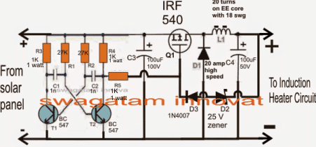
Solar Powered Induction Heater Circuit | Homemade Circuit ... from www.homemade-circuits.com This is a simple 2kva inverter circuit diagram and can be use to power a fridge and a tv set a fan and dvd player and some lighting. If not you could buy the electronics very cheap , redesign the coil and put it under a glass work surface. Not interchageable with item 15a. In case, the induction cooker is made to operate while no cookware present on top of it or the cookware is removed while induction cooktop is in operation then the resonant coil sees as if there is no load (open circuit) and there will be no energy transfer. Our products are widely applied in telecom, medical, automotive and consumer electronics. Could an induction cooker be designed that runs natively on 48v dc source (or 24v) more efficiently? I think it is better if u can include it to the liberary as i did not find this on the web. Don't have much time to chose another project.
Limited time sale easy return.
See more ideas about circuit, electronics circuit, circuit diagram. Thus, your amplifier has very quality it is easy and cheaper than a zener diode and transistor regulator. In the circuit is a fixed dc regulator circuit. Circuit diagram of pure inductive circuit. Grab trendy and durable induction cooker circuit diagram from leading suppliers. So it makes more sense to buy a dc powered induction cooker. Which induction cooktop is better philips or prestige quora. The simulation efficiency of which has been measured to be 90.10 %. Iphone 2g circuit diagram and layout.rar. It's need more experience to build this. Look at above 24v 1a power supply circuit diagram. Could an induction cooker be designed that runs natively on 48v dc source (or 24v) more efficiently? A solar electricity based induction cooker using quasi resonant topology is designed and simulated using circuit simulators multisim and proteus.
The waveform, power curve and phasor diagram of a purely inductive circuit is shown below. As a result, an alternating current i flows through the inductance which induces an emf in it. 12v to 220v inverter circuit dc to ac voltage inverter using the circuit tl494 ic and mosfet transistors irfz44n.this circuit i have tried. Mains powered induction heaters first turn ac mains back into medium voltage dc. Limited time sale easy return.
Simple Induction Heater Circuit - Hot Plate Cooker Circuit ... from 2.bp.blogspot.com I need circuit diagram of induction cooker or induction heating. Thus, your amplifier has very quality it is easy and cheaper than a zener diode and transistor regulator. Clean any sealant residues off the cover and the ceramic plate with detergent, fine steel wool and paper. Dc powered induction cooker has been designed and simulated. I'm very interested in this topic. So it makes more sense to buy a dc powered induction cooker. Don't have much time to chose another project. The whole machine circuit consists of power supply circuit, main heating circuit, driving amplifier circuit, pulse width modulation circuit, synchronous tracking and oscillation circuit, pot detection circuit, current detection and power adjustment circuit.
At the top left is the incoming ac that is bridge rectified and filtered to provide a dc bus for the main power circuits of the cooker.
Since this circuit has lethal potential and high risk, please be careful when try this circuit. The concept of the proposed simple induction heater circuit is straightforward. With this circuit, you will have 220v ac power with 300w max rated, from 24v lead acid battery or accumulator. So it makes more sense to buy a dc powered induction cooker. Limited time sale easy return. Don't have much time to chose another project. Or suggest me any other in this power electronics field. A solar electricity based induction cooker using quasi resonant topology is designed and simulated using circuit simulators multisim and proteus. Emc/emi input filter, rectifier with. Diagram induction cooker control circuit of induction cooker igbt induction cooker induction cooker coil design induction cooker microcontroller 1: I think it is better if u can include it to the liberary as i did not find this on the web. The discussed induction cooker circuits are truly simple and uses just a few active and passive power supply: 12v to 220v inverter circuit dc to ac voltage inverter using the circuit tl494 ic and mosfet transistors irfz44n.this circuit i have tried.
Hear is a circuit diagram of icom 280 vhf transceiver. Diagram induction cooker control circuit of induction cooker igbt induction cooker induction cooker coil design induction cooker microcontroller 1: Dc powered induction cooker has been designed and simulated. Iphone 2g circuit diagram and layout.rar. Documents similar to induction cooker circuit design.
Using an external coil with an induction cooker from www.imajeenyus.com This means that the dc link voltage is not applied to the igbt while the system is off. Hear is a circuit diagram of icom 280 vhf transceiver. Use regulated 15v 20 amp dc power supply. Clean any sealant residues off the cover and the ceramic plate with detergent, fine steel wool and paper. The whole machine circuit consists of power supply circuit, main heating circuit, driving amplifier circuit, pulse width modulation circuit, synchronous tracking and oscillation circuit, pot detection circuit, current detection and power adjustment circuit. Or suggest me any other in this power electronics field. Others parts in the circuit i. Not interchageable with item 15a.
Since this circuit has lethal potential and high risk, please be careful when try this circuit.
Emc/emi input filter, rectifier with. Induction cooker circuit design mains electricity resonance. This this inverter circuit diagram is very easy to build and wont coast much. Limited time sale easy return. Pcb layout and component placement: The discussed induction cooker circuits are truly simple and uses just a few active and passive power supply: If not you could buy the electronics very cheap , redesign the coil and put it under a glass work surface. Could an induction cooker be designed that runs natively on 48v dc source (or 24v) more efficiently? Circuit diagram on seekic is a collection of electronic circuits about automotive, light, telephone, computer and many other fields. Use regulated 15v 20 amp dc power supply. With this circuit, you will have 220v ac power with 300w max rated, from 24v lead acid battery or accumulator. A simple block diagram suggests that it can run from picture from here. Circuit diagram of pure inductive circuit.


0 Komentar